How Water Utilities Can Implement Bi-Annual Testing to Ensure 99%+ System Uptime

TL;DR Executive Summary
Remote Terminal Units (RTUs) are the backbone of lift station monitoring and wastewater telemetry, but without bi-annual preventive maintenance, they fail silently, leaving your system vulnerable to overflows, contamination events, and regulatory violations. A comprehensive RTU maintenance protocol tests five critical components: high-level float switches, backup battery capacity, digital/analog inputs, alarm call-out lists, and tank control logic. Following Mission Communications’ proven maintenance schedule reduces emergency service calls by 40% and extends RTU operational life by 5+ years.
The Hidden Cost of Neglected RTU Maintenance
Water utility managers often treat RTU maintenance as if-it-is-not-broken-do-not-touch. This reactive approach creates a dangerous blind spot. A failed float switch might not trigger an alarm. A degraded battery might fail during a power outage. A misconfigured call-out list might send alerts to an employee who left six months ago. By the time an operator discovers the problem, it is often during an actual emergency—when a 15-minute response delay turns a manageable high-water event into an overflow incident.
According to AWWA (American Water Works Association) standards, utilities performing quarterly or bi-annual RTU testing experience 68% fewer unplanned outages than those relying on manual monitoring alone. For rural utilities especially, where staffing is often stretched thin, a single SCADA failure can cascade into hours of lost monitoring and operational chaos.
How Bi-Annual RTU Testing Prevents System Failures
The Mission Communications RTU maintenance protocol is built on a simple principle: test the entire end-to-end alarm chain twice yearly (spring and fall), in normal operating mode, not service mode. This verifies not just that sensors work, but that alarms actually reach the right person at the right time. Unlike passive voltage monitoring (which many RTUs perform internally), active testing reveals wiring failures, misconfigured call-out schedules, and battery degradation before they cause outages.
Component 1: High-Level Float Testing—Your First Line of Defense
The high-level float switch is deceptively simple: a mechanical device that moves up and down with water level. Yet it is also the most failure-prone component in lift station telemetry. Over time, floats fail due to:
- Mechanical obstruction (caught on ladder rungs, debris in the wet well)
- Electrical degradation (corroded contacts, loose or damaged wiring)
- Material fatigue (plastic brittleness, metal rust, cable strain)
To test: manually lift the float to simulate a high-water alarm. Do not use the RTU’s service mode—keep it in normal operating mode so you verify the complete notification chain. Hold the float in the up position and wait for the alarm notification (call, email, SMS). If the alarm arrives, the float and wiring are functioning correctly. If no alarm arrives but the RTU’s LED illuminates, then there is either an issue with communication from the RTU, a disabled-for-notification input, or an issue the notification schedule. If neither the alarm nor the LED activates, the float has failed and should be replaced.
Note: Check for any delays that might be present in the RTU configuration. Even a 2-minute delay could indicate a false failure if it does not call out. The float should be held for the duration of that delay period, if present, before the call out.
Component 2: Backup Battery Capacity—Your Insurance Against Power Loss
A 12V backup battery is critical for maintaining telemetry during grid outages. However, internal voltage monitoring is not a real-world load test. Batteries degrade silently; a battery can read 12V under no load but collapse to 8V when the RTU demands power during an outage.
To test: turn off AC power to the RTU for 6–10 minutes. The RTU should immediately switch to battery power and transmit an AC Failure alarm. You should receive this notification within 5 minutes. If the alarm arrives, your battery has sufficient capacity. If not, the battery is failing or the charger is malfunctioning. Additionally, use a voltmeter to check battery terminals directly—the reading should be 12V or higher. Any reading below 11.5V indicates a battery that should be replaced within the month. As a rule of thumb, replace all backup batteries every 5 years, regardless of voltage readings, to prevent unexpected failures.
When measuring battery voltage with a voltmeter on a MyDro RTU, the positive lead should be disconnected to prevent measuring the charge circuit voltage. Legacy RTUs only charge once an hour, indicated by the BAT LED blinking on the board. But remove the positive lead anyway for good measure.
Component 3: Sensor Inputs and Calibration Verification
If your RTU monitors analog sensors (pressure transducers, flow meters, level sensors) or digital inputs (pump run hours, valve status), bi-annual testing must include verifying these readings are accurate and within expected ranges. Sensor drift is insidious: a pressure transducer that is off by 5% might not trigger alarms, but it introduces cumulative error into your operational data.
During maintenance, cross-check RTU readings against physical instruments (a separate pressure gauge, flow meter, or water level staff). If readings diverge by more than 2%, recalibrate the sensor or replace it. Also review your analog setpoints: thresholds that were appropriate five years ago may no longer match your utility’s current operational limits. Update setpoints to reflect today’s peak-demand scenarios and peak seasonal flows.
Component 4: Alarm Call-Out Lists—Ensuring Alarms Reach Real People
An alarm that reaches the wrong person (or no one) is functionally equivalent to no alarm at all. Staff turnover, phone number changes, and email migrations happen constantly. A call-out list that has not been audited in 12 months is almost certainly stale.
Action items: (1) Log into 123SCADA and review every phone number and email in the call-out list. Verify that each contact is still employed and reachable at the listed number. (2) Delete login credentials for departed staff immediately. (3) Ensure all new operators have been provisioned with web access and trained on system controls. (4) Update primary and secondary operator contact lists quarterly, not just bi-annually. (5) Consider implementing encrypted SMS or push notification fallback channels in addition to email, to reduce the risk of a single communication channel failure.
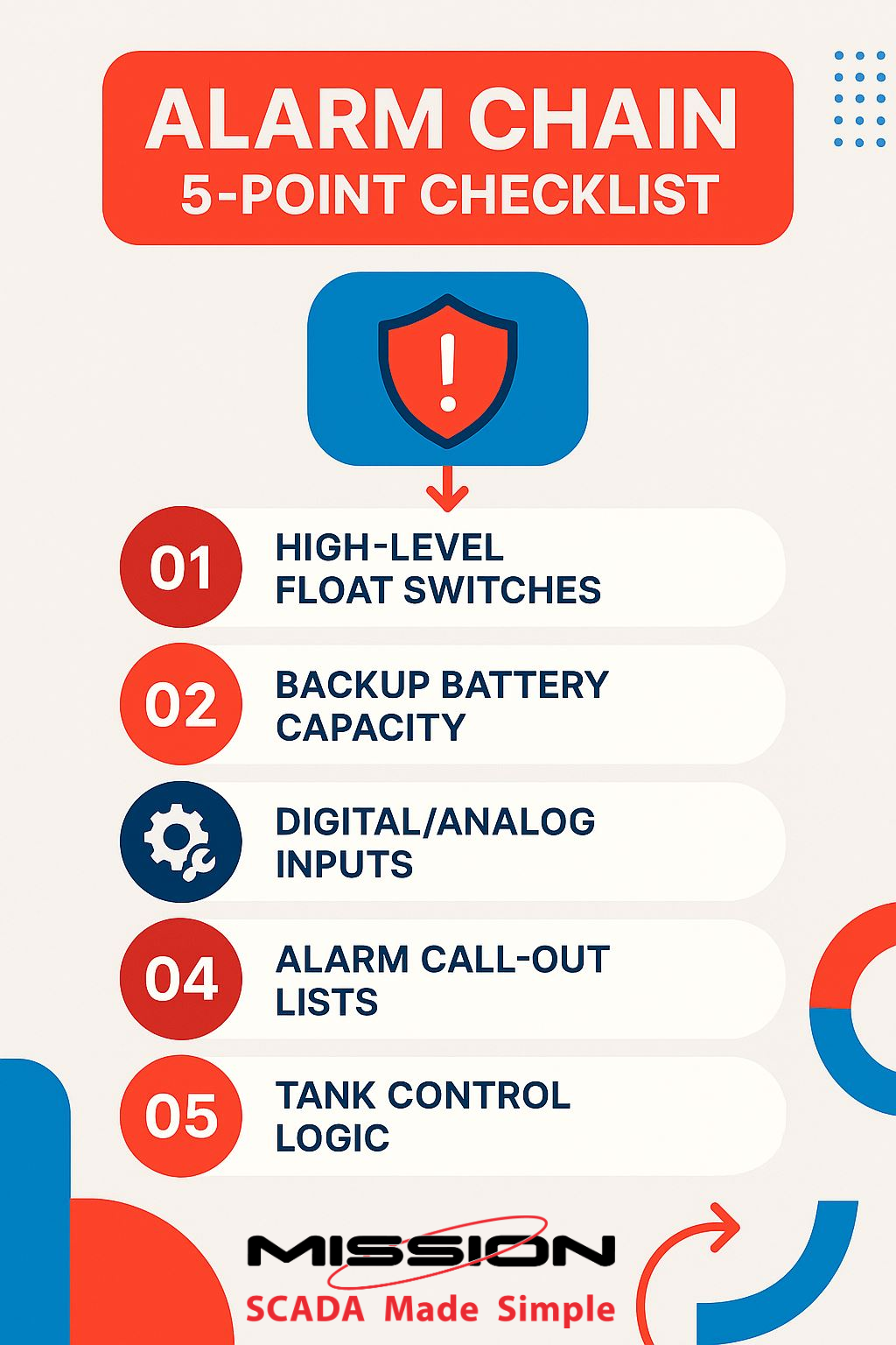
Component 5: Active Control Logic Testing—For Pump Control Systems
If your RTU manages pump operation based on tank levels (enabling or disabling well pumps when water level crosses a setpoint), you must test this control logic actively. Do not rely on historical data or assumptions about how the system behaves.
To test: (1) Disable well pumps either manually at the site or via the web interface. (2) Allow the tank to drain naturally to the low-level alarm setpoint. (3) Verify that you receive a low-level alarm notification when the threshold is crossed. (4) Re-enable pumps and verify the tank refills without error. (5) Test secondary sensors or dual-pump configurations to ensure redundancy is operational. (6) Conduct a brief training session with all operators on web interface controls so they are comfortable executing manual pump control during an emergency.
Real-World Impact: Why One Water District Shifted to Bi-Annual Testing
A rural water district in the Midwest managed 47 lift stations across a service area of 12,000 customers. For three years, they performed RTU maintenance only when operators reported problems. Downtime was sporadic but frequent: an average of 2–3 unplanned outages per station annually, each lasting 2–4 hours.
In late 2022, one lift station’s high-level float failed silently during spring. The RTU had been transmitting data normally, but the float switch was stuck, preventing any alarm if water level rose. One week later, heavy rains caused the wet well to overflow, contaminating a neighboring property and triggering an EPA inspection. The district faced regulatory penalties and a spike in customer complaints.
The district implemented Mission Communications’ bi-annual RTU testing protocol. Starting that fall, maintenance crews visited all 47 stations in October and April, executing the same five-point checklist each time. Within the first year of testing, crews discovered: 8 degraded float switches, 3 backup batteries nearing end-of-life, and 12 outdated phone numbers in call-out lists. All issues were corrected before they could cause operational failures. Over the next two years, unplanned outages dropped to fewer than 0.5 per station annually. More importantly, the district restored public confidence and avoided future regulatory incidents.
Technical Specifications & Testing Standards
| Component | Testing Requirement |
|---|---|
| High-Level Float Switch | Manually lift and verify alarm receipt in normal operating mode; visual inspection for corrosion or obstruction |
| Backup Battery (12V) | Load test: kill AC power for 6+ min; verify AC Failure alarm within 5 min. Voltmeter check must read >= 12V. Replace every 5 years or if voltage < 11.5V. |
| Digital & Analog Sensors | Cross-verify readings against independent instruments; acceptable tolerance +/- 2%. Review and update setpoints annually. |
| Call-Out Configuration | Audit all phone numbers and email addresses; test alarm transmission to primary and secondary contacts; delete inactive user logins. |
| Active Control Logic | If applicable: disable pumps, allow tank to drain to alarm level, verify low-level notification. Train all operators on manual control. |
Alignment with Industry Standards
RTU maintenance practices should align with AWWA (American Water Works Association) standards for remote monitoring and NIST Cybersecurity Framework guidelines for operational technology (OT) asset management. The EPA’s Water Infrastructure Finance and Innovation Act (WIFIA) emphasizes that utilities investing in preventive maintenance reduce overall lifecycle costs and improve service reliability. Mission Communications’ maintenance protocol is designed to meet or exceed these standards.
The Human Element: Insights from Field Technicians
“In 15 years of SCADA field work, I have learned that the utilities that survive emergencies are the ones that test proactively. The float that fails during a test is the float that is replaced before it can cause an overflow. I cannot tell you how many times I have arrived at a site after a problem call and thought, ‘This would have been caught in maintenance.’ It is not glamorous work, but it saves careers and reputations.”
— Lead SCADA Technician, Midwest Water District
Quick-Start: 90-Day Implementation Timeline
Week 1–2: Audit all RTUs and create a site inventory. Identify which stations have floats, sensors, and backup batteries. Document current call-out lists.
Week 3–4: Train all operators on the five-point testing protocol. Conduct first round of testing at 2–3 pilot sites.
Week 5–8: Roll out testing across all stations. Document findings and initiate any repairs (battery replacement, float cleaning, wiring fixes).
Week 9–12: Schedule second testing round for the following season (spring or fall). Establish a recurring calendar reminder for bi-annual maintenance.
Frequently Asked Questions
Q: How long does a complete bi-annual RTU test take per station?
A: Typically 30–45 minutes per station, depending on complexity. If all systems are functioning normally, you may complete testing in 20–30 minutes. If issues are discovered (e.g., wiring problems, dead battery), repair and troubleshooting can add 1–2 hours. Plan for 1 hour per station on average.
Q: Can we skip testing one year if operations have been stable?
A: No. Silent failures are the biggest risk. A float can be mechanically stuck for months without affecting normal system operation, yet a single high-water event will expose the failure. Bi-annual testing is preventive; its value lies in catching problems before they manifest as outages. Skipping one year negates the cumulative benefit of the program.
Q: What should we do if testing reveals a failed component?
A: Replace or repair immediately. A failed float switch or dead backup battery should be treated as an emergency repair, not a deferred maintenance item. Temporary workarounds (e.g., manual level checks) may be acceptable for 24–48 hours, but long-term operation with a known failed component invites disaster. Mission Communications can provide emergency replacement parts and remote troubleshooting support if needed.
Q: How do we know if our backup battery is truly ready for an extended outage?
A: The voltmeter check (12V or higher) is a good indicator, but a real-world load test is the only true validation. By shutting off AC power and letting the RTU run on battery for 6–10 minutes, you are simulating exactly what happens during a grid outage. If the RTU continues to transmit alarms and maintain connectivity during this test, the battery is good. If performance degrades, the battery should be replaced.
The Bottom Line
Bi-annual RTU testing is not a luxury—it is a foundational practice that separates utilities that experience routine outages from those that achieve 99%+ uptime. By testing the complete alarm chain twice yearly, you catch failures before they cascade into emergencies, extend your hardware lifespan, train your operators, and protect your community. The cost of a few hours of maintenance in spring and fall is infinitesimal compared to the cost of an overflow incident, regulatory penalties, or customer dissatisfaction.
Ready to implement a systematic maintenance program? Mission Communications’ technical support team is here to guide you through every step. Call us at (877) 993-1911, contact your local Mission Distributor or email our support team to schedule a maintenance consultation.
Mission Communications | 123SCADA | Managed SCADA for Rural Water & Wastewater Utilities